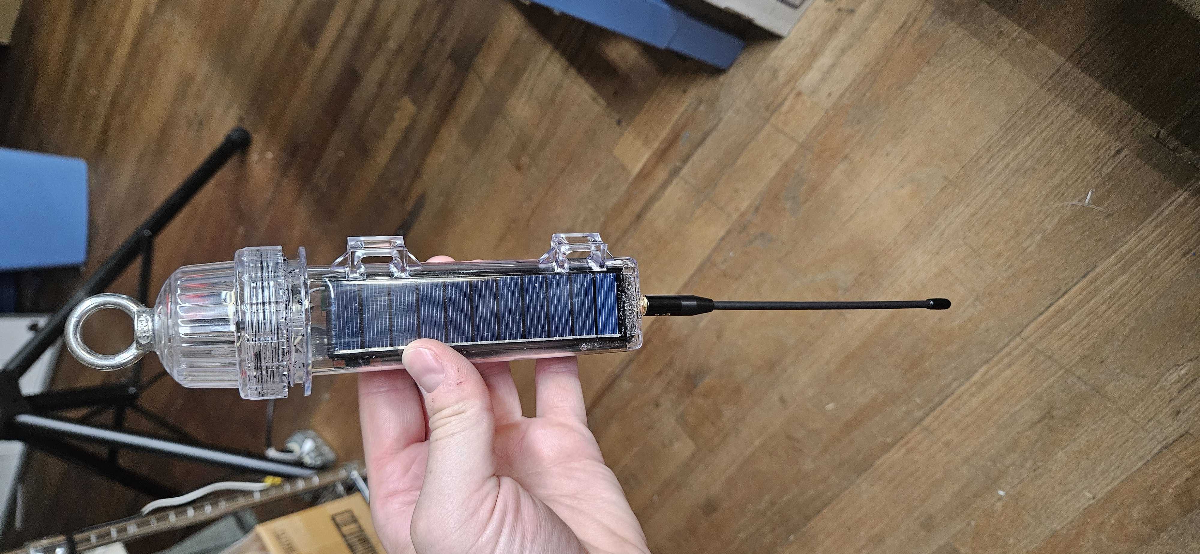
Solar Buoy Micro Mesh Node
Platform: MeshCore / Seeed Studio XIAO nRF52840
Overview
An ultra-compact, solar-powered off-grid repeater built by modifying a commercial solar buoy light enclosure. Designed specifically for MeshCore, this node features a direct bottom-mounted whip antenna for line-of-sight coverage without RF obstruction from the casing, along with a stainless steel top eyebolt for tree, mast, or overhead hanging deployment. Inspired by the PhillyMesh solar buoy design.
Parts & Reference Links
- Donor Housing & Base: Solar Buoy Light (AliExpress)
- Battery Protection: 1S Li-ion BMS Module (Amazon)
- Solar Charging: Mini MPPT Solar Charger Board (AliExpress)
- Core Microcontroller & Radio: Seeed Studio XIAO nRF52840 + SX1262 Kit (Seeed Studio)
- Bootloader: Adafruit_nRF52_Bootloader_OTAFIX (GitHub)
- Hanging Hardware: Stainless Steel Eyebolts (Amazon)
- Firmware: ZephCore MeshCore Port (GitHub)
- Design Inspiration: PhillyMesh Solar Buoy Writeup (GitHub)
Component Breakdown
| Category | Component Description | Source / Detail |
|---|---|---|
| Enclosure | Weatherproof clear cylindrical housing, threaded cap, & solar panels | Donated from solar buoy light |
| Power Storage | Single-cell Li-ion/LiPo battery | Donated from solar buoy light |
| Charging & Management | Mini MPPT Solar Charger Board (Square module) | Added (Link) |
| Protection | 1S Li-ion Battery Protection Board / BMS (Round module) | Added (Link) |
| Logic & Radio | Seeed Studio XIAO nRF52840 + SX1262 Board Stack | Added |
| Control | Mini SPST Slide Switch | Added (Hot-leg power isolation) |
| RF / Antenna | 6"+ IPEX/U.FL to SMA female bulkhead pigtail + Muzi whip antenna | Added |
| Hardware / Insulation | Heatshrink tubing, clear silicone, 1/4" Stainless Steel Eyebolt, washers, lockwashers, nuts, blue Threadlocker | Added |
Build & Assembly Steps
Step 1: Solar Wiring & Enclosure Base Modification
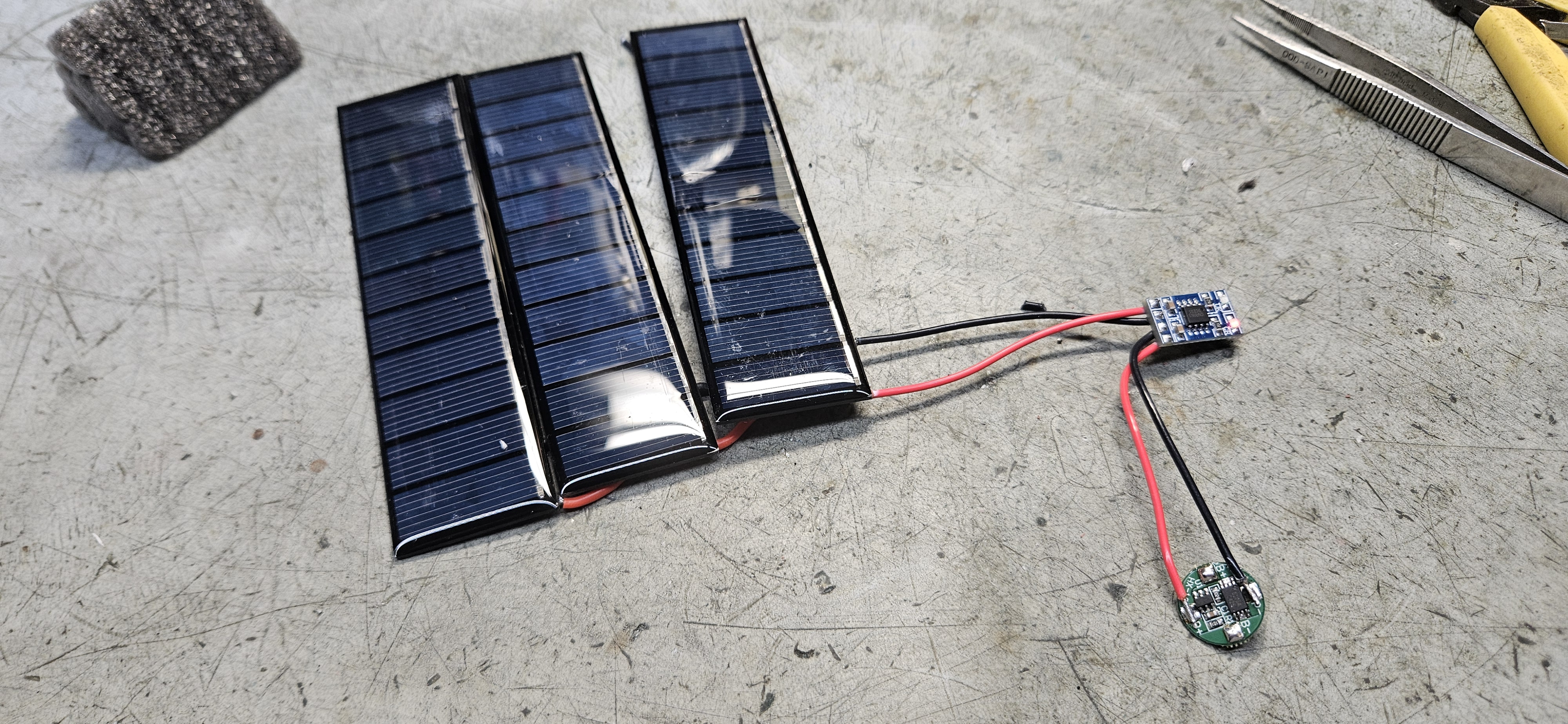
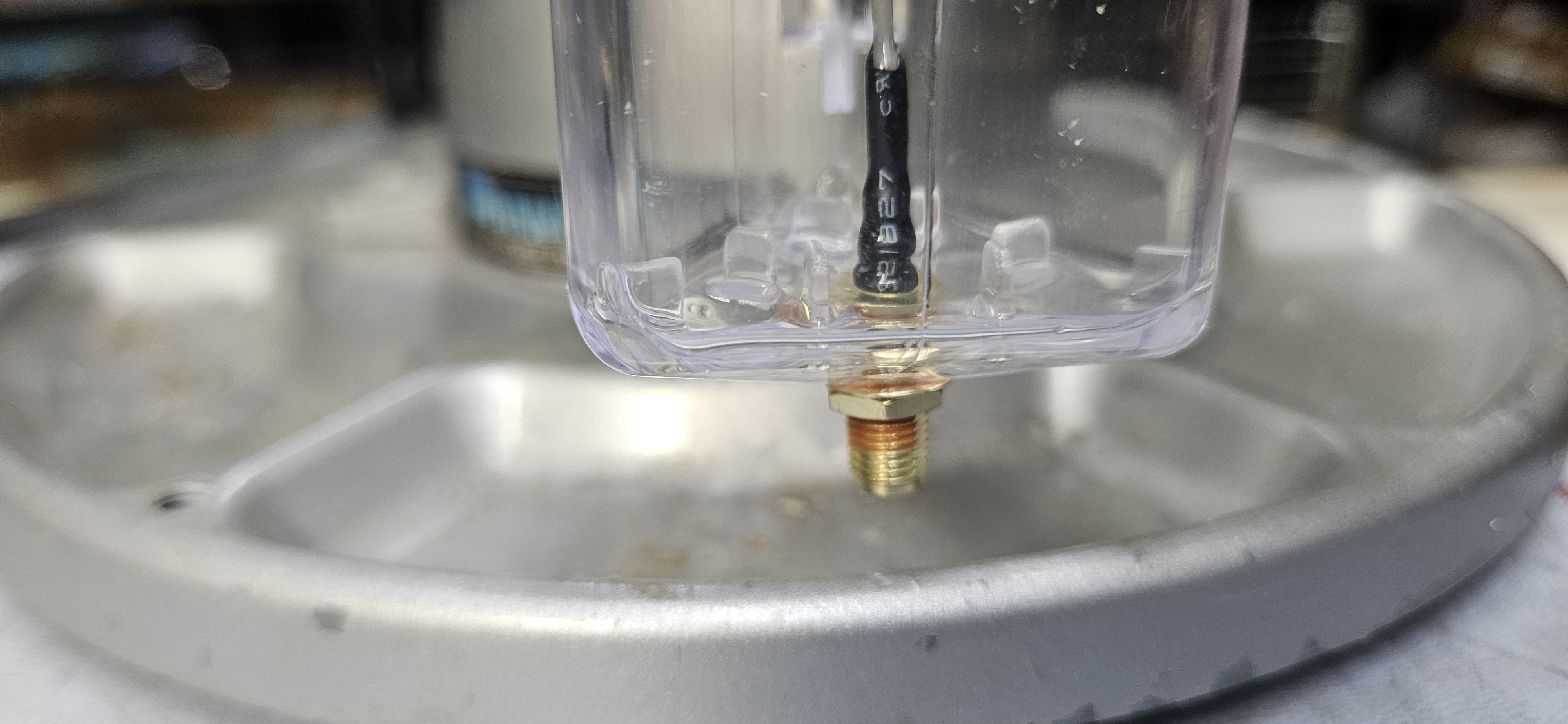
Wire the integrated mini solar cell array to the input terminals of the MPPT charger module (square board). Drill a 1/4" hole through the bottom center of the clear buoy light cylinder. Pass an IPEX/U.FL to SMA female bulkhead pigtail (minimum 6" cable length with pre-applied heat shrink) through the base hole.
Secure the bulkhead with a toothed lockwasher and blue Threadlocker on the threads, applying clear silicone sealant inside and out to guarantee a weatherproof seal.
Step 2: Coaxial Strain Relief & Core Cushioning
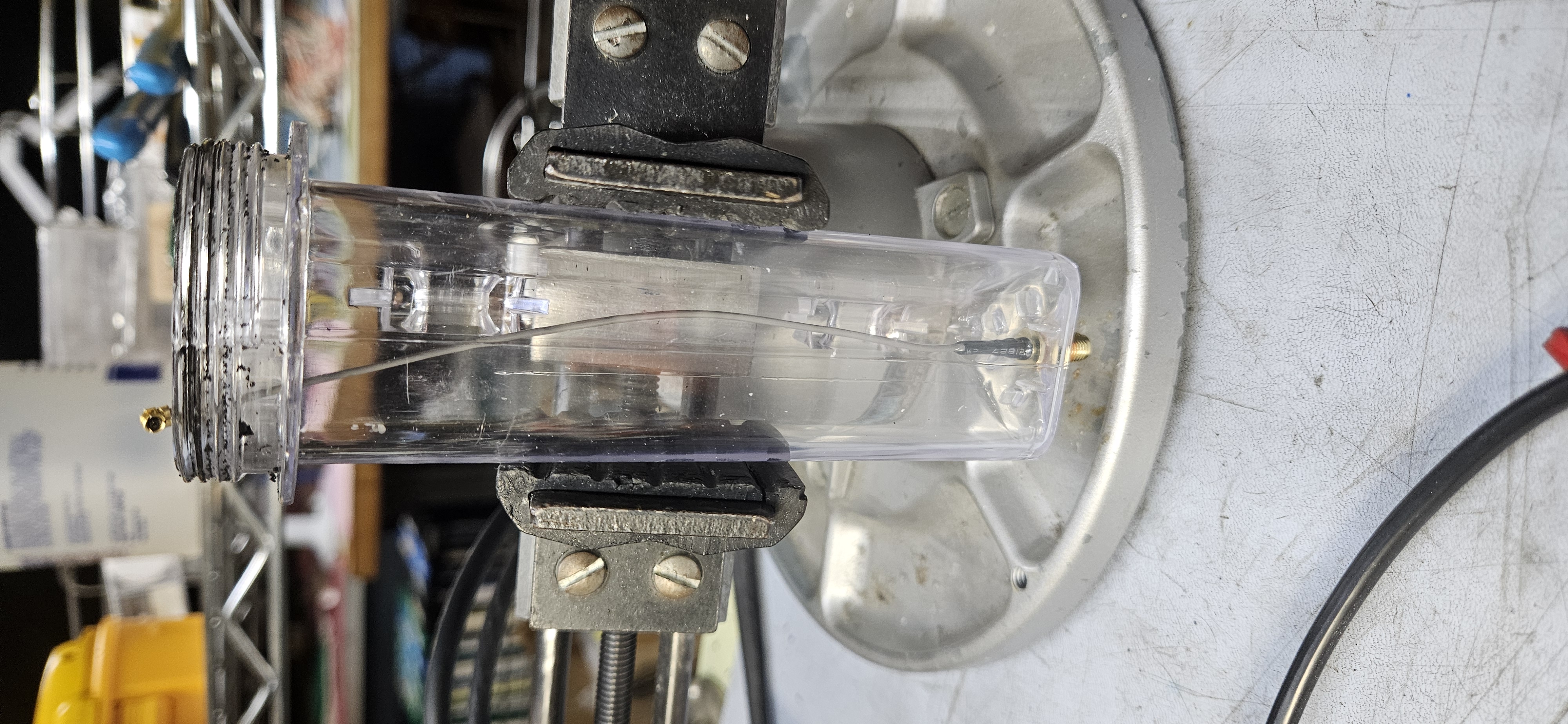
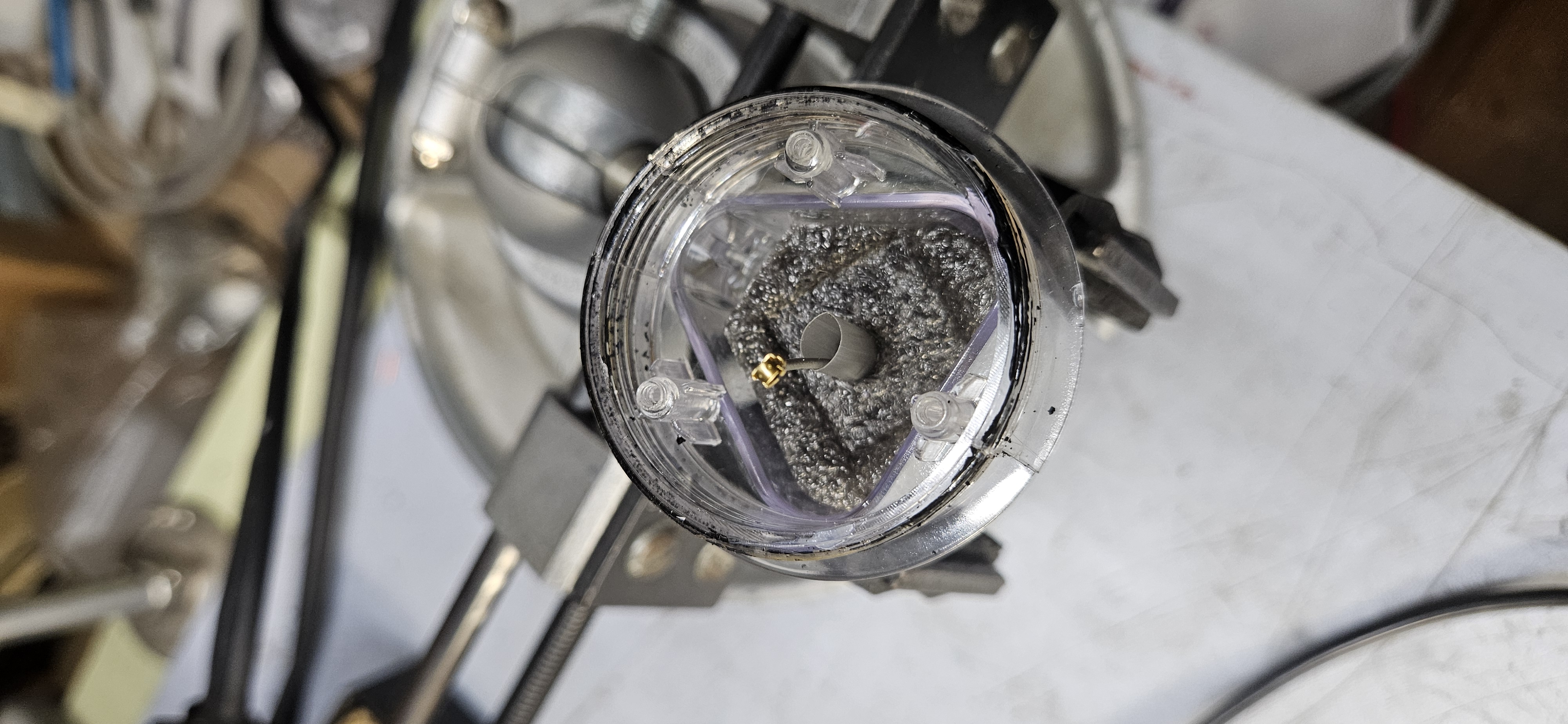
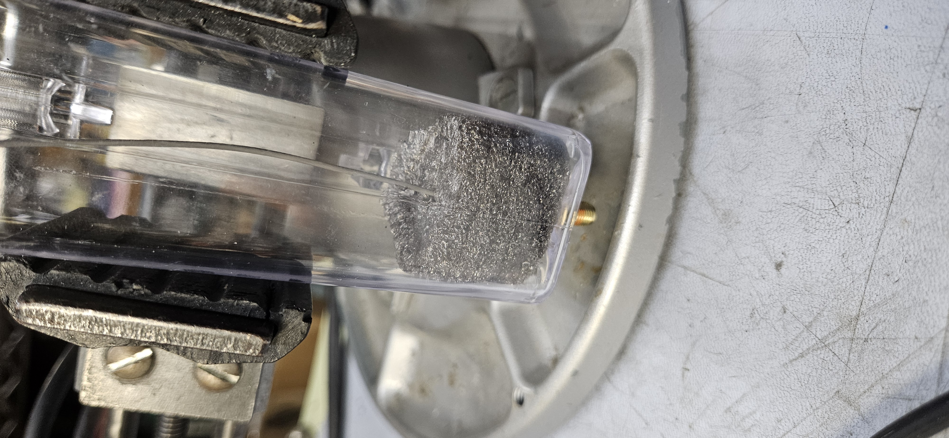
Trim the original donor buoy foam block down to size and pierce a pass-through hole through its center. Route the pigtail cable up through the trimmed foam block.
Ensure the foam height is trimmed just tall enough to cushion the internal core assembly without placing a tight bend radius on the coaxial cable exiting the SMA connector base.
Step 3: Solar & Power Circuit Insulation
Connect the integrated single-cell battery through the round 1S BMS module for cell protection. Encapsulate both the BMS and MPPT boards in heatshrink tubing before final placement to prevent short circuits against adjacent components inside the compact tube.
Install an inline SPST slide switch on the hot leg of the battery output on the upper deck to act as a main power cutoff.
Step 4: Microcontroller Header Trimming & Logic Deck Isolation
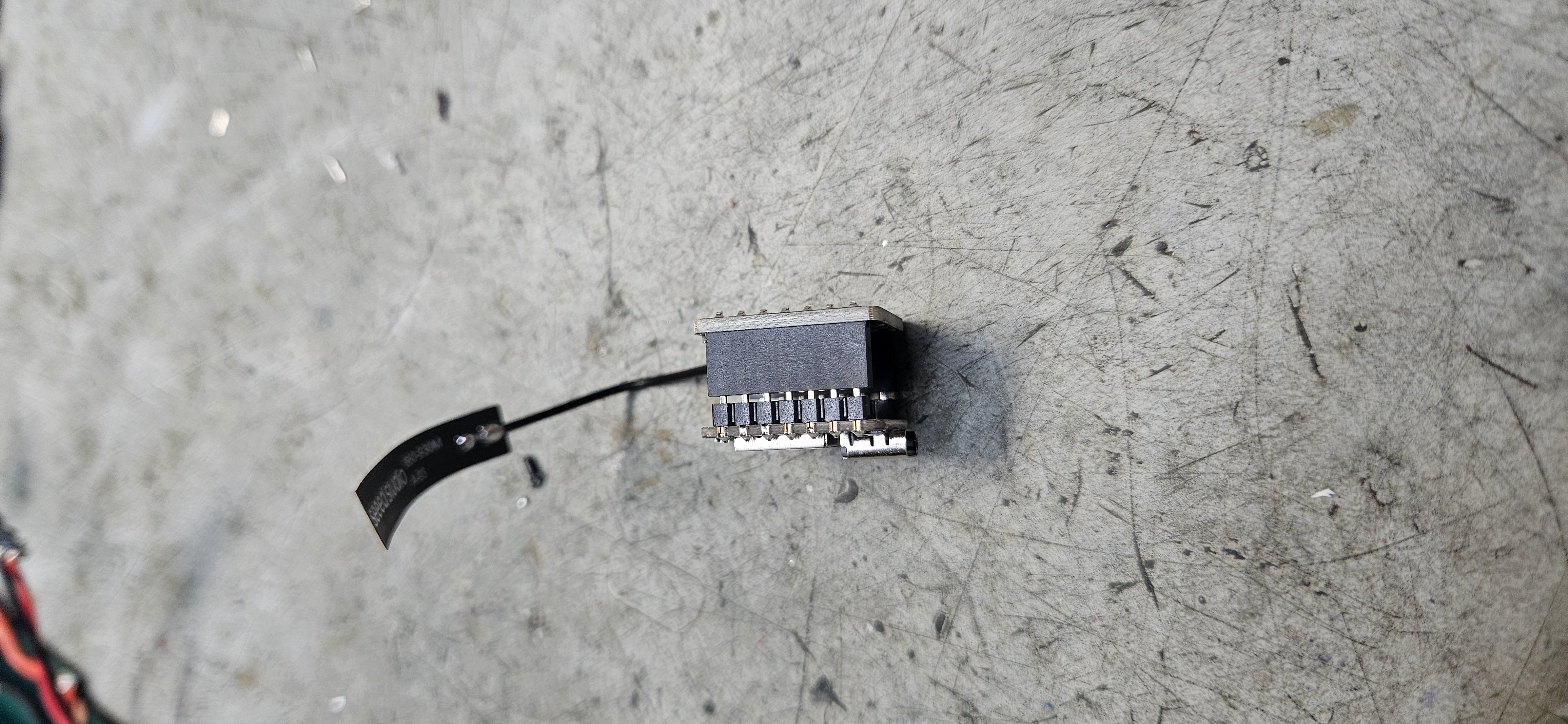
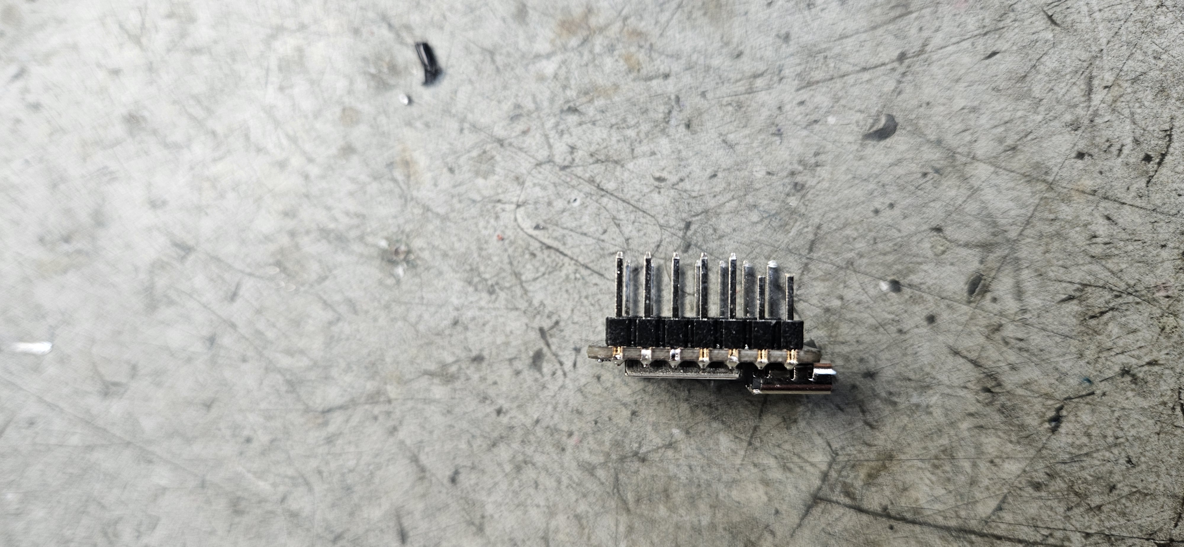
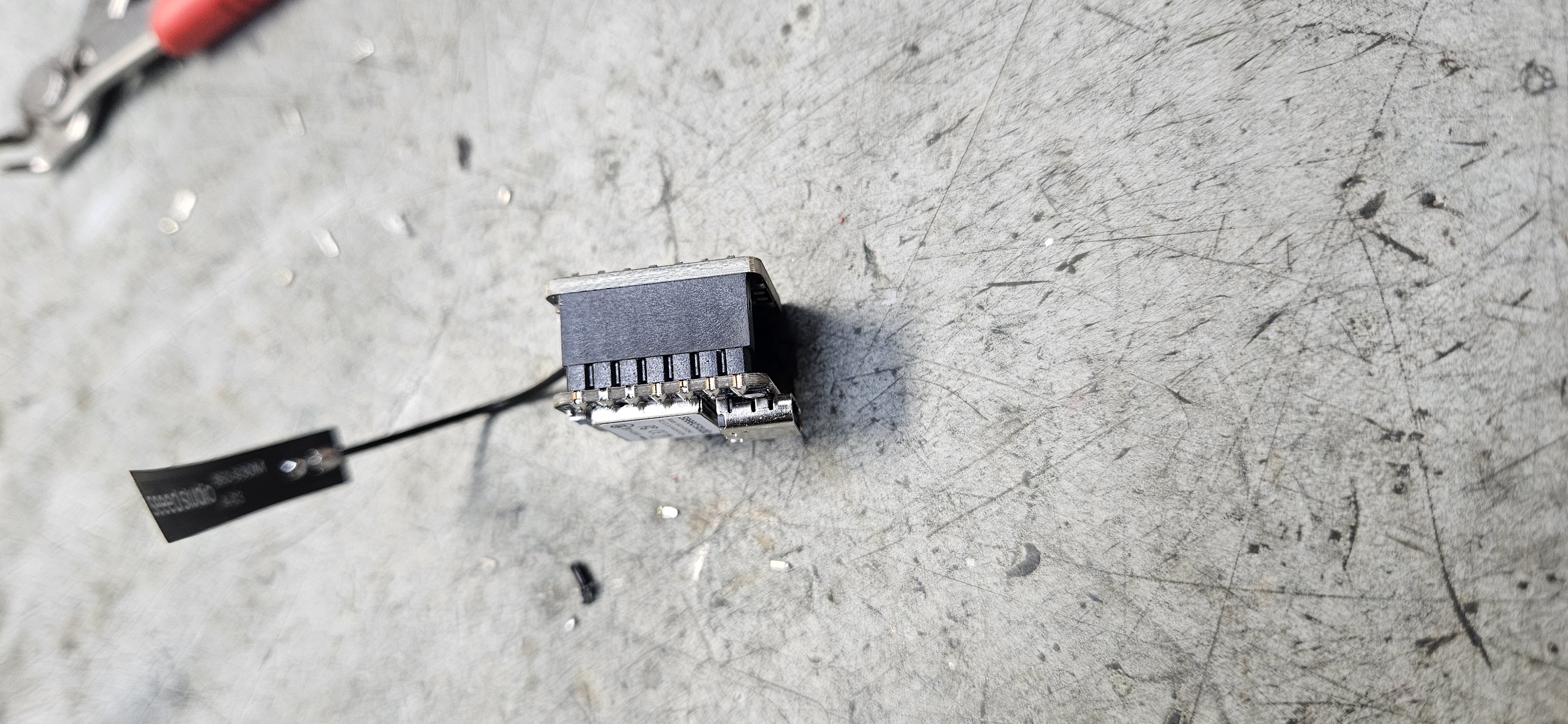
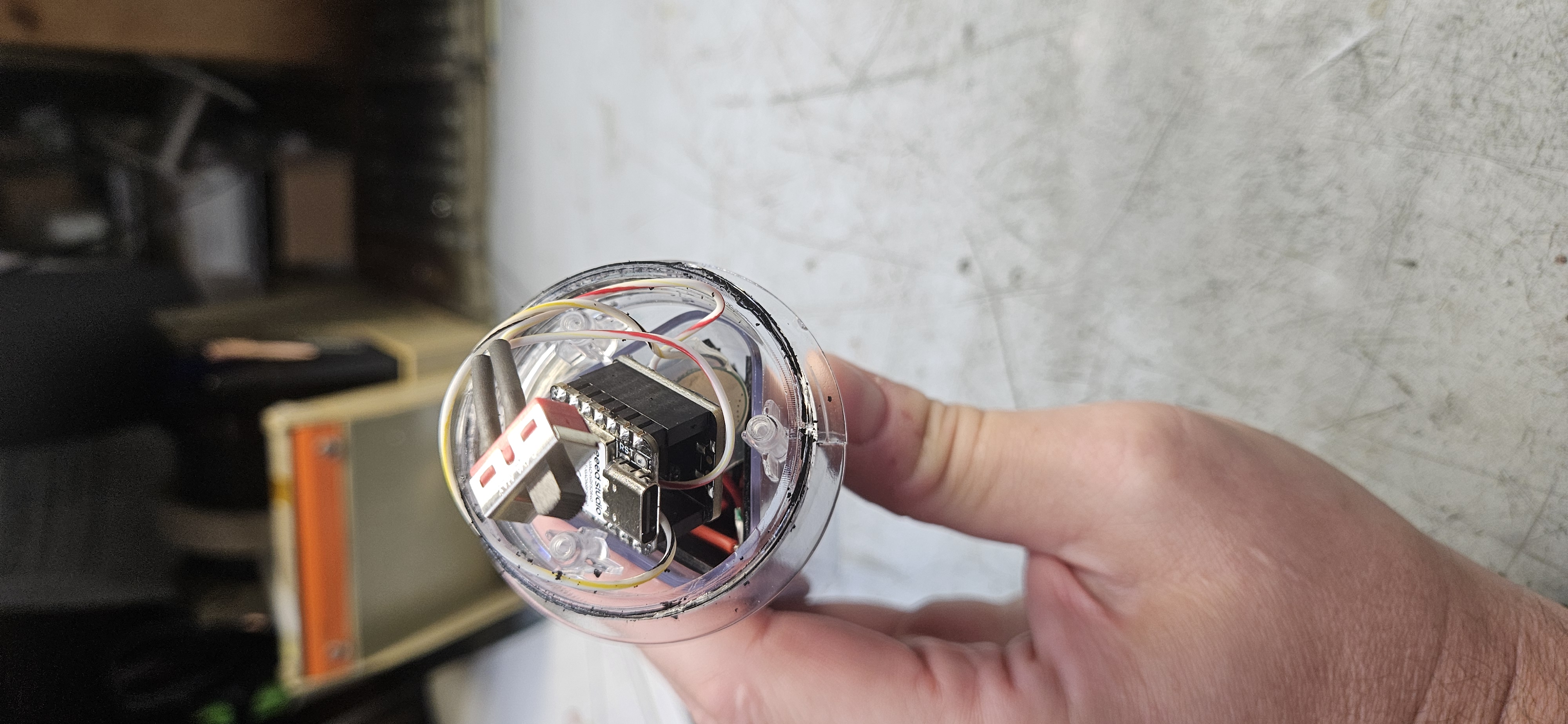
Clip the bottom pins off the radio module board and trim a small portion off the Seeed Studio XIAO’s pre-attached header pins to allow the two boards to mate as flush as possible. Apply a layer of clear silicone over the clipped pin stubs on the bottom of the radio board to fully insulate the exposed metal and eliminate short risks.
Plug the two boards together tightly to minimize total vertical height inside the narrow cylinder. Snap the U.FL antenna connector onto the XIAO board, then anchor it with a dab of clear silicone sealant (or hot glue) to prevent vibration-induced disconnects.
Step 5: Top Cap & Weatherproof Hanging Assembly
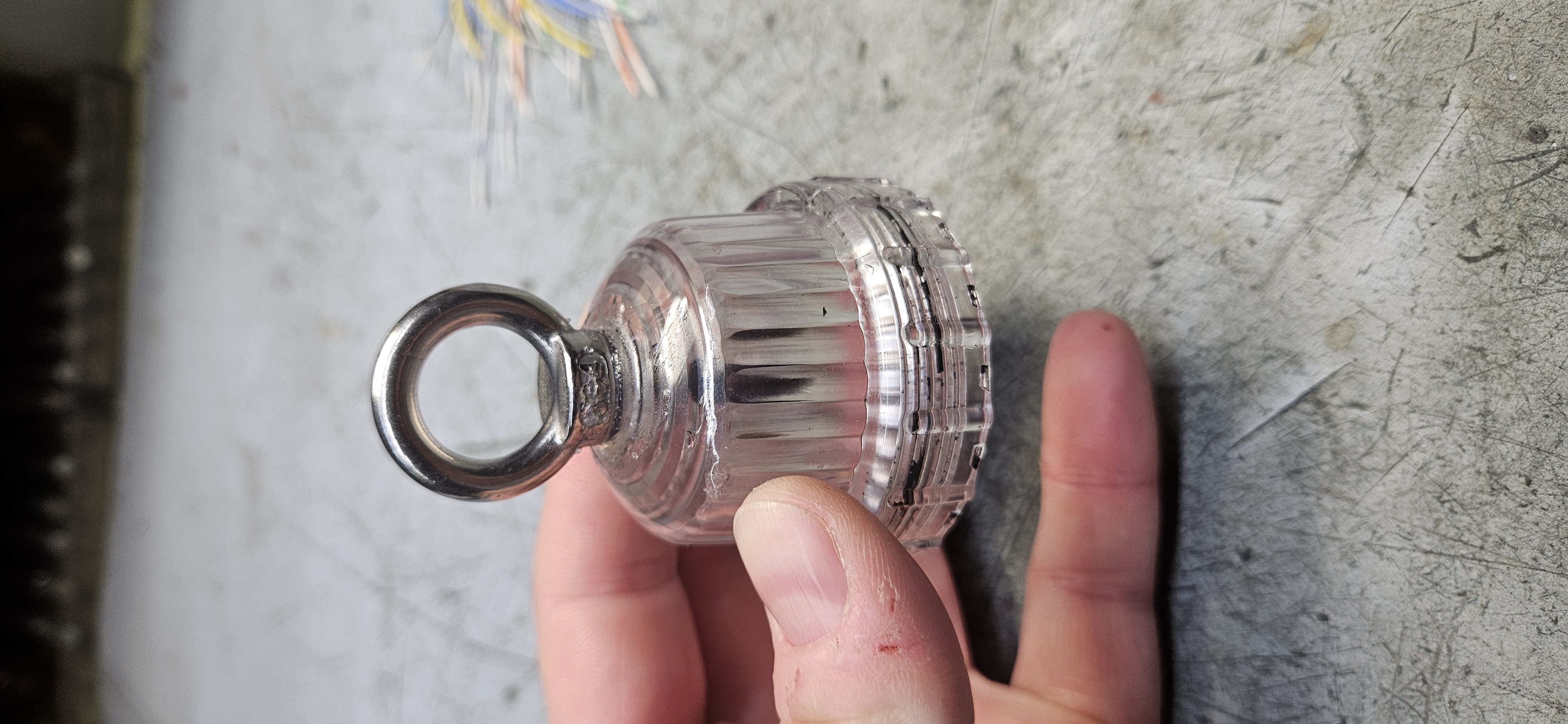
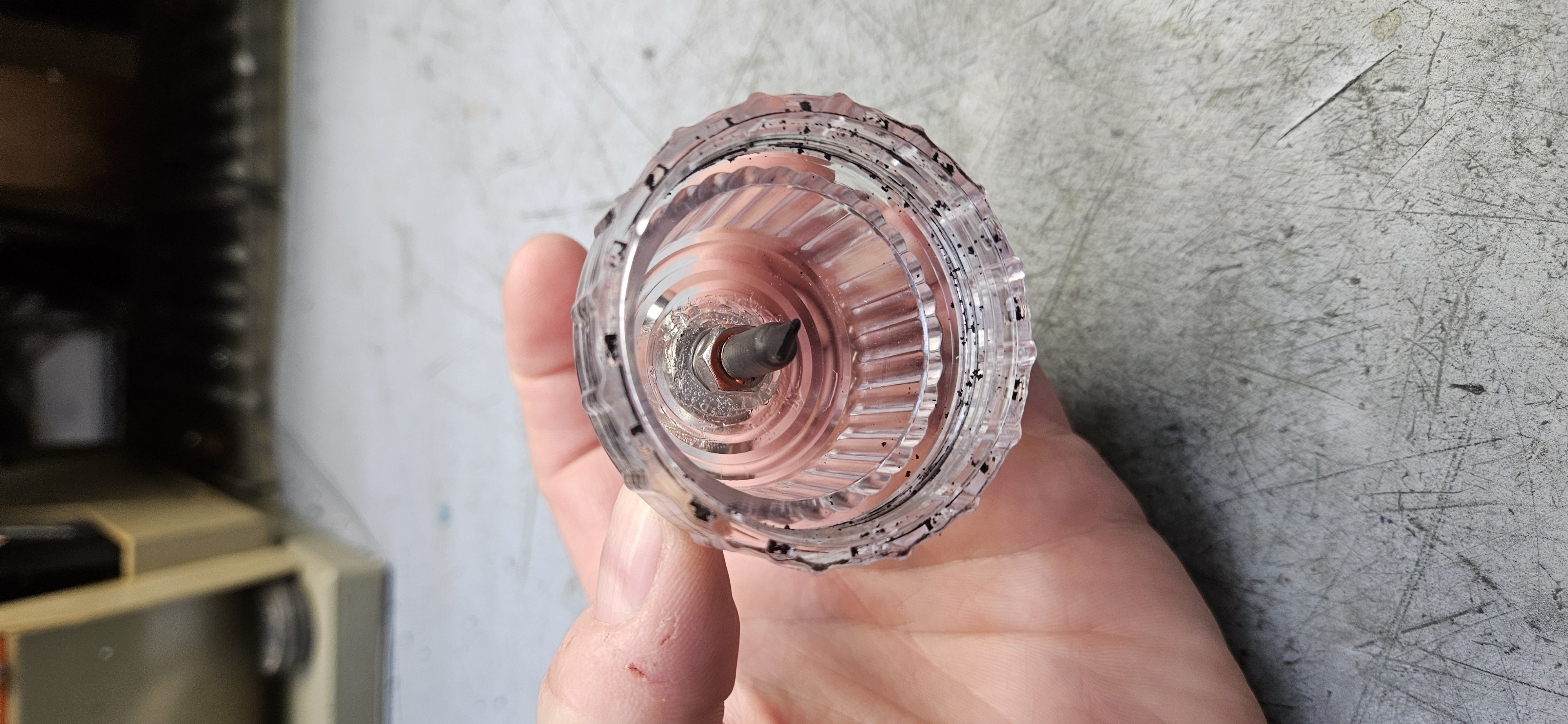
Drill a 1/4" hole through the apex of the clear threaded top cap. Install the stainless steel eyebolt using a washer, lockwasher, nut, and blue Threadlocker on the hardware threads.
Seal the eyebolt assembly thoroughly inside and out with clear silicone sealant. Re-lubricate and seal the main threads before closing up the housing.
Step 6: Enclosure Integration & Switch Placement
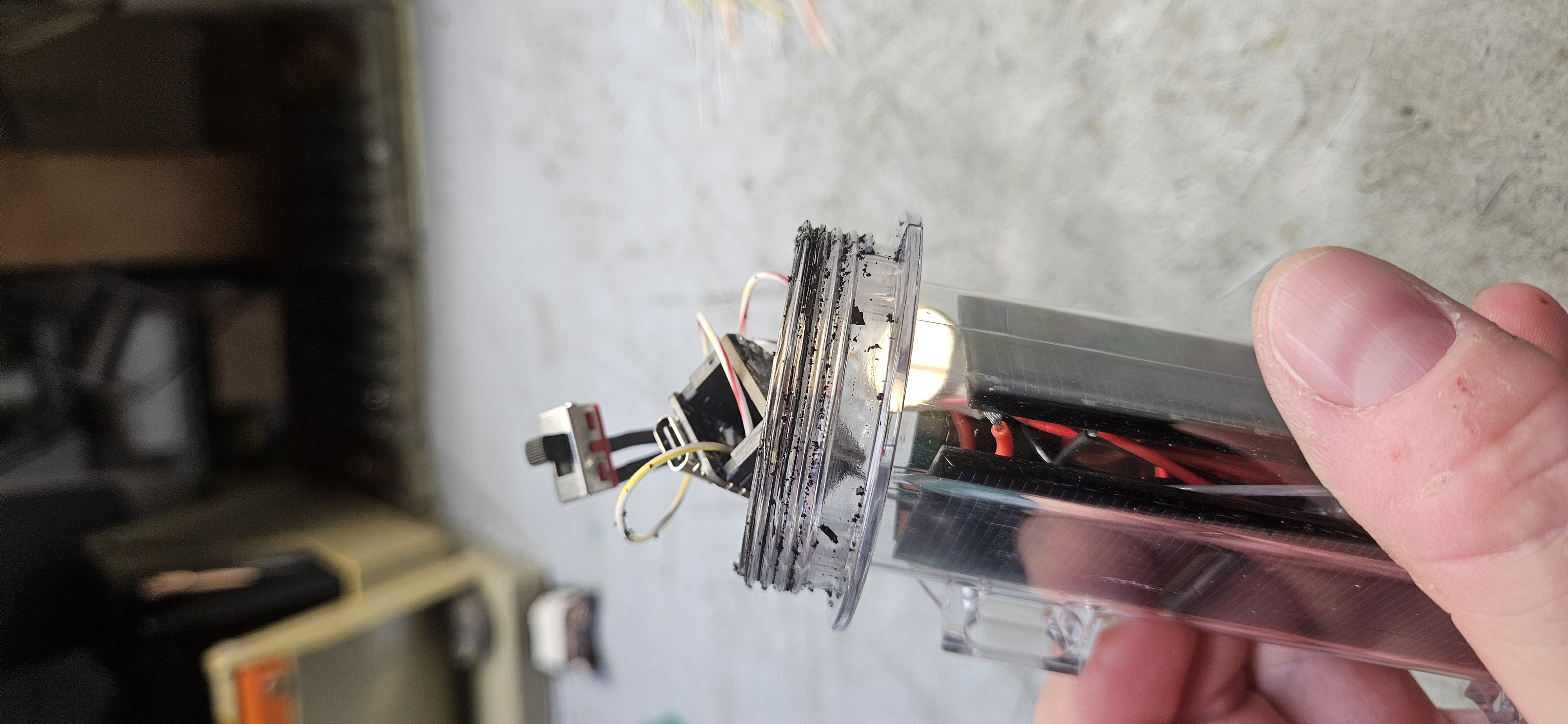
Slide the entire core stack into the clear cylinder, ensuring all components sit securely without pinching wires. Position the SPST power switch right at the top of the opening for easy access when the cap is unscrewed.
Step 7: Flashing, Safety Checks & Final Deployment
Update Bootloader: Double-tap the reset button on the XIAO nRF52840 board to put it into bootloader mode, then drag and drop the .uf2 file from the Adafruit_nRF52_Bootloader_OTAFIX repository onto the mounted drive.
Flash Firmware: Flash the node with the ZephCore MeshCore port before final enclosure sealing.
Verify solar charging and radio transmission, screw on the top cap, and suspend the completed node via the stainless steel top loop.